4.5 Attribute matrix of multiple layers - LUPMISManual
Main menu:
4.5 Attribute Matrix of Multiple Layers
Level of expertise required for this Chapter: Expert; general Map Maker training
If you have two or more vector layers, which you want to use in a quantitative way to interpret, you want an attribute table with all the individual layers’ characteristics. This process of land evaluation is very useful for planning purposes (see also Chapter 7.8).
For example, you have a soil map, a climatic map, a slope map and a land use map, and want all the individual styles numbers (mapping units) combined in the attribute table of one layer.
There are two ‘approaches’:
Recommended: Intersect --> Inherit --> Transfer to attribute table (and rename of data column) --> Repeat inherit and transfer for all maps --> Merge all new attribute tables (see Part 1/A below)
- Alternative: Transfer all to attribute tables --> Intersect with transfer of attribute (and rename of data column) --> Repeat for all maps --> Merge all new attribute tables (see Part 1/B below)
After this process, data can be manipulated in the attribute table (for example, in Excel), using a wide range of mathematical formulas (see Part 2 below).
The display of the processed data is the last step (see Part 3 below).
If there is any technical problem with the Intersect module, as described below, use the external module Intersect.exe in folder C:\Map Maker (see installation Annex 1.1.1 and 1.5).
- - - -
1) Approach 1 (recommended):
1.1 Intersect the two maps: Main menu > Utilities > Vector utilities > Intersect / unite files > Intersect lines and polygons window: Add file > Select map 1 > Add file > Select map 2 > Do not tick: Find intersections > Tick: Tidy boundaries > Execute > Save result as > Specify new filename (such Temp_overlaid) > Save > Quit
Note 1: If you have more than 2 maps to overlay, you continue in the previous step with Add file > Select map x.
Note 2: If there is any error message with the Intersect / Unite files module, use the separate Intersect.exe module (delivered by HQ).
Note 3: Have a thorough look at the file, you just created. Clean up very small polygons, delete sliver polygons, use the nested polygon correction at the live layer options.
1.2 Inherit styles from map 1: Main menu > File > Clear > Right-mouse > Project Manager > Project manager window: Add layer > Select layer of step 1.1 (such as Temp_overlaid) > Open > Copy layer to live layer > OK
Right-mouse > Live layer actions > Live layer actions window: Spatial queries > Inherit attributes from other file > OK > Inherit attributes from other file window: Polygon file > Select map 1 > Open > Tick ‘Inherit styles’ > Don’t tick ‘Inherit label’ > OK
Right-mouse > Save live layer as... > Specify new filename (such as Temp_overlaid_1) > Save > Save
1.3 Repeat step 1.2 for map 2 and any additional maps, but save it to new file(s) (such as Temp_overlaid_2, ...3 etc)
1.4 Transfer these style numbers to an attribute table: Main menu > Utilities > Database utilities > Generate database from DRA > Select layer of previous step 1.2 (such as Temp_overlaid_1) > Open > General database... window: Tick: Style number > OK > Specify new filename (such as Temp_overlaid_1_attr) > Save
1.5 Repeat step 1.4 for map 2 and any additional maps, but save it to new file(s) (such as Temp_overlaid_2_attr, ...3_attr etc)
1.6 Rename the column (field) of this new attribute file: Main menu > Utilities > Database utilities > Edit database > Select file of previous step 1.4 (such as Temp_overlaid_1_attr) > Open > Select column STYLE > Edit columns > Change column definition > Column definition window: Change field name to STYLE_1 > OK > OK
1.7 Repeat step 1.6 for map 2 and any additional maps, but change field name to new name(s) (such as STYLE_2, STYLE_3 etc)
1.8 Add map to live layer: Main menu > File > Clear > Right-mouse > Project Manager > Project manager window: Add layer > Select layer of step 1.1 (such as Temp_overlaid) > Open > Copy layer to live layer > OK
1.9 Merge table of map 1: Main menu > Edit > Live layer data > Merge data table with live data > Select attribute file of step 1.6 above (such as Temp_overlaid_1_attr) > Open > Choose link column window: Select ID > Leave both tick boxes on > OK > Pick columns to import window > Tick STYLE_1 > OK
1.10 Repeat step 1.9 for map 2 and any additional maps, but select file(s) of step 1.7 (such as Temp_overlaid_2_attr, ...3_attr etc) with styles accordingly.
1.11 Save under new filename (such as Temp_overlaid_all).The attribute file will be saved as a DBF file, which can be opened in Excel.
Continue with Part B below.
- - - - -
1A) Approach 2 (alternative):
1.1A. Have map 1 ready with all style numbers
1.2A. Transfer the style numbers of map 1 to an attribute table: Main menu > Utilities > Database utilities > Generate database from DRA > Select map 1 > Open > General database... window: Tick: Style number > OK > Specify new filename (such as Temp_1_attr) > Save
1.3A. Have map 2 ready with all style numbers
1.4A. Transfer the style numbers of map 2 to an attribute table: Main menu > Utilities > Database utilities > Generate database from DRA > Select map 2 > Open > General database... window: Tick: Style number > OK > Specify new filename (such as Temp_2_attr) > Save
1.5A. Intersect map 1 and 2, generating attributes for all intersected units from map 1 attributes: Main menu > Utilities > Vector utilities > Intersect / unite files > Intersect lines and polygons window: Add file > Select map 1 > Add file > Select map 2 > Select map 1 at the listing > Tick: Find intersections > Tick: Tidy boundaries > Tick: Inherit attribute data > Choose attribute data for (map 1) > Select file of step 1.2A above (such as Temp_1_attr) > Choose link column window: ID > OK > Columns to import: Tick: STYLE > Execute > Save result as > Specify new filename (such Temp_1_overlaid) > Specify new filename for DBF file (such as Temp_1_overlaid) > Quit
1.6A. Rename the column (field) of this new attribute file: Main menu > Utilities > Database utilities > Edit database > Select file of step 1.5A above (such as Temp_1_overlaid) > Open > Select column STYLE > Edit columns > Change column definition > Column definition window: Change field name to STYLE_1 > OK > OK
1.7A. Repeat intersecting map 1 and 2, but this time generating attributes for all intersected units from map 2 attributes: Main menu > Utilities > Vector utilities > Intersect / unite files > Intersect lines and polygons window: Add file > Select map 1 > Add file > Select map 2 > Select map 2 at the listing > Tick: Find intersections > Tick: Tidy boundaries > Tick: Inherit attribute data > Choose attribute data for (map 2) > Select file of step 1.4A above (such as Temp_2_attr) > Choose link column window: ID > OK > Columns to import: Tick: STYLE > Execute > Save result as > Specify new filename (such Temp_2_overlaid) > Specify new filename for DBF file (such as Temp_2_overlaid) > Quit
1.8A. Rename the column (field) of this new attribute file: Main menu > Utilities > Database utilities > Edit database > Select file of step 1.7A above (such as Temp_2_overlaid) > Open > Select column STYLE > Edit columns > Change column definition > Column definition window: Change field name to STYLE_2 > OK > OK
1.9A. Add map to live layer: Right-mouse > Project Manager > Project manager window: Add layer > Select layer of step 1.5A (such as Temp_1_overlaid) > Open > Copy layer to live layer > OK
1.10A. Merge table of map 1: Main menu > Edit > Live layer data > Merge data table with live data > Select attribute file of step 1.5A above (such as Temp_1_overlaid) > Open > Choose link column window: Select Serial > Leave both tick boxes on > OK > Pick columns to import window > Tick STYLE_1 > OK
1.11A. Merge table of map 2: Main menu > Edit > Live layer data > Merge data table with live data > Select attribute file of step 1.7A above (such as Temp_2_overlaid) > Open > Choose link column window: Select Serial > Leave both tick boxes on > OK > Pick columns to import window > Tick STYLE_2 > OK
1.12A. Save under new filename. The attribute file will be saved as a DBF file, which can be opened in Excel.
- - - -
2) See graphics below, how data can be manipulated, for example in Excel, to calculate the mean, or maximum, or any formula, for each mapping unit (row). For more instructions on spreadsheet formulae, see explanations in Chapter 7.8.
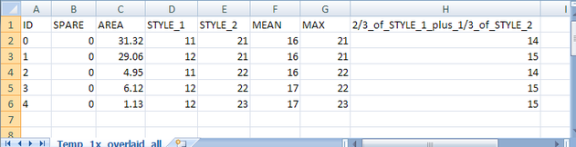
If you are well familiar with Excel and need arises for more complex land evaluation applications, you can express relations (including overruling exclusions and weighted averages) with if-formulas.
For example: If map 1 (in STYLE_1) has a 99, result is 0. If map 2 (in STYLE_2) has a 99, result is 1. If map 1 has a value greater than 15, this value has 3x the weight than of map 2, otherwise the mean of map 1 and map 2 is taken. Don’t forget to round afterwards (column G below).
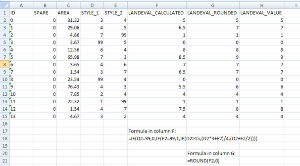
It is recommended to have the column, which is to be used for import into Map Maker, as value, not as formula (column H in sample above, process in Excel: Copy cells (with formula) > Paste Special > Paste as Value and check, that they are numbers, not text.
- - - - -
If you made any changes in Excel 2007, you can’t save it back as DBF file. Instead, you save it as XLS file, then in Map Maker, after you have loaded the DRA file (such as Temp_overlaid_all) and copied it to livelayer: Main menu > Edit > Live layer data > Merge data table with live data > Files of type: XLS > Select XLS file, which you just edited in Excel > Open > Choose table window: Select file > Leave both ticks on > OK > Choose link column window: ID > Leave both ticks on > OK > Pick columns to import window: Select all > OK.
Don’t forget to save the live layer.
- - - - -
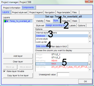
3) For the display, based on these data, you select at the Project manager window: Layers > Style (1, see below) > Assign according to... (2) > Database (3) > Data column (4) > Select column (5) > OK