LUPMIS - GIS User Manual for Land Use Planning
Main menu:
- Home Page
- 0. Rationale
- 1. GIS handling
- 2. GIS data entry
- 2.1 Create new layer
- 2.2 Digitize line
- 2.3 Digitize point
- 2.4 Digitize polygon
- 2.5 Edit existing layer
- 2.6 Delete feature
- 2.7 Split line
- 2.8 Split polygon
- 2.9 Merge lines from different layers
- 2.10 Unite lines
- 2.11 Snap lines
- 2.12 Join polygons
- 2.13 Extend polygon
- 2.14 Insert island
- 2.15 Define unit surrounding islands
- 2.16 Create 'doughnut'
- 2.17 Fill 'doughnut' polygon
- 2.18 Fill polygon with 'holes'
- 2.19 Digitize parcels from sector layout
- 3. GIS operations
- 3.1 Create buffer
- 3.2 Create exclusion zone
- 3.3 Overlay units
- 3.4 Convert line to polygon
- 3.5 Derive statistics (area size, length)
- 3.6 Clip unit according to other unit
- 3.7 Create geographic grid
- 3.8 Move entire vector map
- 3.9 Move or copy individual features on a map
- 3.10 Adjust polygon to line
- 3.11 Convert points to polygon
- 3.12 Define by distance
- 3.13 Create multiple objects
- 4. Attribute database
- 4.1 Start with database
- 4.2 Import database
- 4.3 Display database information
- 4.4 Enter attribute data
- 4.5 Attribute matrix of multiple layers
- 4.6 Seeds
- 4.7 Repair attribute data
- 4.8 Merge lines with attached database
- 4.9 Transfer attribute data from points to polygons
- 4.10 Copy styles, labels, attributes
- 5. Conversion of data
- 5.1 Points
- 5.1.1 Import list of points from text file
- 5.1.2 Import list of points from Excel file
- 5.1.3 Convert point coordinates between projections
- 5.1.4 Convert point coordinates from Ghana War Office (feet)
- 5.1.5 Convert point coordinates from Ghana Clark 1880 (feet)
- 5.1.6 Track with GPS
- 5.1.7 Download GPS track from Garmin
- 5.1.8 Download GPS track from PDA
- 5.2 Vector maps
- 5.3 Raster maps
- 5.4 Communication with other GIS programs
- 5.4.1 Import GIS data from SHP format
- 5.4.2 Import GIS data from E00 format
- 5.4.3 Import GIS data from AutoCAD
- 5.4.4 Export LUPMIS data to other programs
- 5.4.5 Export GIS to AutoCAD
- 5.4.6 Change a shape file to GPX
- 5.4.7 Transfer GIS data to other LUPMIS installations
- 5.4.8 Digitize lines in Google Earth
- 5.5 Drawing Tools
- 5.6 Terrain data
- 5.1 Points
- 6. Presentation
- 7. GIS for land use planning
- 8. Database
- Annexes
- A1. Map Maker setup
- A2. Background to cartography and raster images
- A3. Glosssary
- A4. Troubleshooting
- A5. Styles
- A6. Classification for land use mapping and planning
- A7. GIS utilities
- A8. Map projection parameters
- A9. Maps in pilot areas
- A10.Standards
- A11. LUPMIS distribution CD
- A12. Garmin GPS
- A13. Training
- A14. ArcView
- A15. Population statistics
- A16. Entry and display of survey data
- A17. External exercises
- A18. MS Access
- A19. Paper sizes
- A20. Site map and references
5.5.1 Lines
5. Conversion of data > 5.5 Drawing Tools
5.5 Drawing Tools
Level of expertise required for this Chapter: Intermediate; specifically for LUPMIS @ TCPD
![]()
If you want to draw features (parcels, lines, points, planning templates) in accurate terms in meters (distance) / degrees (bearing) or in x / y coordinates, or to modify or want to process or to quality-contol, you can also use the 'Drawing Tools' of LUPMIS. You can go to the 'LUPMIS Tools' here (if installed locally through the InstallationCD).
Like all the 'LUPMIS Tools' ( Printing Tools, Permit Tools, Census Tools), they are not part of the standard Map Maker setup. They have been developed at TCPD for the execution of land use planning in Ghana, to design and to handle parcels at Local Plan level (Planning Permit, drawing of parcels).
Most 'Drawing Tools' create a new DRA file with the requested features in a temporary file (often 'Lupmis_temp_...) in folder C:\LUPMIS\Permits\Temp, displayed at Map Maker. It is upto you to save this temporary file in a permanent location. Additionally, points which have been created and might be useful for future processing, are saved under the same temporary file name with a suffix (ending) of _p.
Note: Technically, it is programmed in php to satisfy future requests on webbased migration of GIS services. It uses MMmacro and GIS file import and export features of Map Maker (loc, xy, mme, ptp and geo files, see also Annex 18.5).
5.5.1 Lines
Following functions available:
- Line
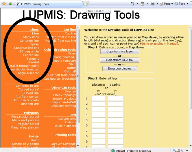
The advantage of this entry is that you can define a line in precise terms, for example as observed by the surveyors in the field. The line starts from a 'start point', which is entered either
- As a point in Map Maker (digitizing a point/symbol), or
- From a point DRAfile (previously digitized point, then saved), or
- From UTM x and y coordinates, which can be entered as numbers.
You then enter the distance / bearing values or the UTM x / y values of each point, which defines the line. But don't mix distance/bearing with x/y. You can define upto 10 points. If you need more entry points, contact TCPD / LUPMIS-HQ.
Define start point > Enter all legs (with distance in meters and bearing, or in UTM with x and y) > Define output file > Execute
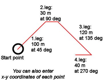
All entered distance / bearings / UTM values are listed in a box in the middle of the form and then again after processing.
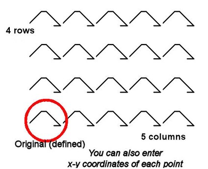
- Many lines
This tool is very similar to the Line tool above, but gives the option to have multiple copies to the right (number of lines in the row) and up (number of rows) of the original line. In addition, you have to enter the distances to the right and up.
In the sample below, 5 copies to the right and 4 copies up were specified. Be aware, that it produces an entire grid of the original feature and all copies have the same distance and bearing values, as you originally entered.
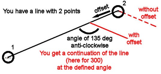
- Continue line
A line can continue in a given angle to the last leg. The angle, direction and length of the continuation line have to be entered.
Sample below shows a continuation of the line (in red) in a relative angle of 135° in anti-clockwise direction from the original line.
You can define an 'offset', if you want to start the 'continuation line' before the endpoint of the original line (circle 2 below).
- Splay
This is the less powerful, but easier version of the previous function 'Continue line'. If you want to set a 'splay', you best use this function (with 3 points: 1 at the corner, 2 and 3 to indicate the direction of the sides of the parcel, and the offset value, i.e. the cutting distance from the corner).
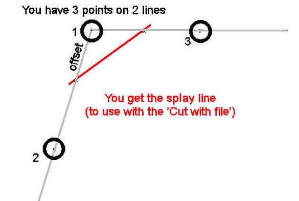
After you have defined the 'splay line', have the layer with the parcel in the live layer (not this splay line!) and Select the parcel to be cut > Edit > Show Selection Manager > Selection Manager window: Actions > Basic operations > Cut with file > Cutter file > Select this splay line file > OK.
There is a similar function, which produces a 'curved' (or round) splay line under ' Arcs'.
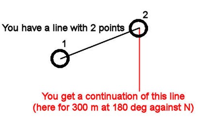
- Continue line (N)
Similar to the previous tool 'Continue line', but the angle is defined as the bearing angle (from N direction).
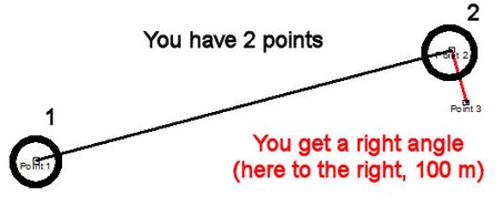
- 90 deg angle
If you want to draw a right angle (90°) in an easy way, you can use this tool. You specify the reference line with 2 points: Number 1 anywhere on the line, number 2 where the right angle should be placed. You also define the length of the new line.
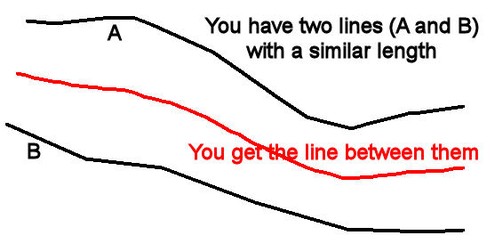
- Center line
If you have two lines of similar (not necessarily same) length, you can have a center line between the two original lines.
The two lines should be in two separate DRA files.
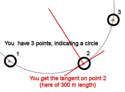
- Tangent
A tangent is the straight line, which 'touches' an arc (or circle) at a given point. It always has a right angle to the radius at the given point.
All you have to do, is to enter 3 points, which define the arc (or circle). The 2nd point is the point, through which the tangent runs. You also specify the length (to each direction) of the tangent line.
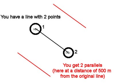
- Parallel
If you need parallels to a line in a defined distance from this line, you use this tools. You define the original line with 2 points anywhere on the line, and the distance of the new parallel(s) to the original line.
As an option, you can select, if you want parallels on both sides, or only one parallel on one side.
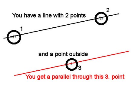
- Parallel through point
This is similar to the tool 'Parallel' above, but you don't enter the distance to the original line in meters, but a point, through which the new parallel should run through.
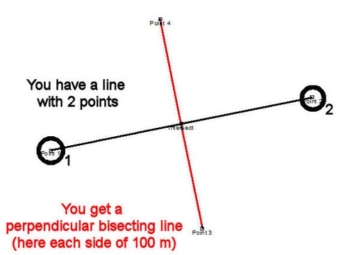
- Perpendicular bisector
A bisecting line cuts half-way through a line between 2 points. You enter the 2 points, between which the bisector should pass, and the length of the bisecting lines on each side (to point 3 and 4, see sample below).
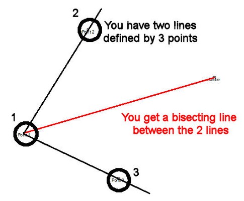
- Angle bisector
An angle bisector is the angle, which cuts half through an existing angle. You define 3 points: Number 1 is the intersection point (centre of the angle), the other two points indicate the angle (direction only).
You also define, how long the bisecting line should be.


Sub-Menu: