LUPMIS - GIS User Manual for Land Use Planning
Main menu:
- Home Page
- 0. Rationale
- 1. GIS handling
- 2. GIS data entry
- 2.1 Create new layer
- 2.2 Digitize line
- 2.3 Digitize point
- 2.4 Digitize polygon
- 2.5 Edit existing layer
- 2.6 Delete feature
- 2.7 Split line
- 2.8 Split polygon
- 2.9 Merge lines from different layers
- 2.10 Unite lines
- 2.11 Snap lines
- 2.12 Join polygons
- 2.13 Extend polygon
- 2.14 Insert island
- 2.15 Define unit surrounding islands
- 2.16 Create 'doughnut'
- 2.17 Fill 'doughnut' polygon
- 2.18 Fill polygon with 'holes'
- 2.19 Digitize parcels from sector layout
- 3. GIS operations
- 3.1 Create buffer
- 3.2 Create exclusion zone
- 3.3 Overlay units
- 3.4 Convert line to polygon
- 3.5 Derive statistics (area size, length)
- 3.6 Clip unit according to other unit
- 3.7 Create geographic grid
- 3.8 Move entire vector map
- 3.9 Move or copy individual features on a map
- 3.10 Adjust polygon to line
- 3.11 Convert points to polygon
- 3.12 Define by distance
- 4. Attribute database
- 4.1 Start with database
- 4.2 Import database
- 4.3 Display database information
- 4.4 Enter attribute data
- 4.5 Attribute matrix of multiple layers
- 4.6 Seeds
- 4.7 Repair attribute data
- 4.8 Merge lines with attached database
- 4.9 Transfer attribute data from points to polygons
- 4.10 Copy styles, labels, attributes
- 5. Conversion of data
- 5.1 Points
- 5.1.1 Import list of points from text file
- 5.1.2 Import list of points from Excel file
- 5.1.3 Convert point coordinates between projections
- 5.1.4 Convert point coordinates from Ghana War Office (feet)
- 5.1.5 Convert point coordinates from Ghana Clark 1880 (feet)
- 5.1.6 Track with GPS
- 5.1.7 Download GPS track from Garmin
- 5.1.8 Download GPS track from PDA
- 5.2 Vector maps
- 5.3 Raster maps
- 5.4 Communication with other GIS programs
- 5.4.1 Import GIS data from SHP format
- 5.4.2 Import GIS data from E00 format
- 5.4.3 Import GIS data from AutoCAD
- 5.4.4 Export LUPMIS data to other programs
- 5.4.5 Export GIS to AutoCAD
- 5.4.6 Change a shape file to GPX
- 5.4.7 Transfer GIS data to other LUPMIS installations
- 5.4.8 Digitize lines in Google Earth
- 5.5 Terrain data
- 5.1 Points
- 6. Presentation
- 7. GIS for land use planning
- 8. Database
- Annexes
- A1. Map Maker setup
- A2. Background to cartography and raster images
- A3. Glosssary
- A4. Troubleshooting
- A5. Styles
- A6. Classification for land use mapping and planning
- A7. GIS utilities
- A8. Map projection parameters
- A9. Maps in pilot areas
- A10.Standards
- A11. LUPMIS distribution CD
- A12. Garmin GPS
- A13. Training
- A14. ArcView
- A15. Population statistics
- A16. Entry and display of survey data
- A17. External exercises
- A18. MS Access
- A19. Paper sizes
- A20. Site map and references
6.2 Styles
6. Presentation
6.2 Styles
Level of expertise required for this Chapter: Intermediate
6.2.1 Background
The general process for the layout and print is: Style --> Legend --> 'Furniture' --> Print
Styles handle the presentation of polygons, lines and points, i.e. the appearance of mapping features in Map Maker. Style sets are organized in style libraries. They define the colours or hatching:
A) Polygons:
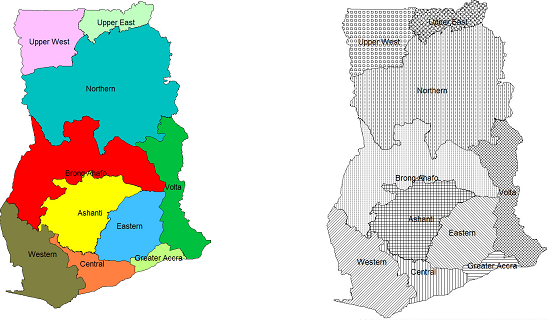
B) Lines:

C) Points:
There are three different levels of style libraries:
A) Default style set: Appears, when you load Map Maker.
Note 1: See step 4 of Annex 1.1.1 for the style installation, Annex 1.1.7 to configure.
B) Theme-specific style sets: For example, for road, altitude etc.
Note 2: All pre-defined libraries of LUPMIS (extension STL) are stored in folder C:\Map Maker\Library or C:\Map Maker\Configuration\Style library, and have self-explanatory names. See Annex 5 , also Note 1 above.
C) Project style set: With all changes of the default style set, saved with the project (see Note 3 of Chapter 1.6, and Chapter 6.6.1).
6.2.2 Source of Style Libraries
Style libraries will be provided by TCPD-HQ / LUPMIS, as the display of mapping features should be standardized for TCPD activities.
But you can also define a new style library through:
Main menu > File > System set up > Styles library > Set up window: Styles library > New style set > Name new library style set window: Enter new name > OK > Proceed with the editing, as explained below > OK
A style set received by copying the file to your computer, has be to imported to your Map Maker by:
Main menu > File > System set up > Styles library > Set up window: (if there is an old one with the same name, this has to be removed first. Then:) Import style set > Select folder and file name > OK
6.2.3 Editing of Style Libraries
If you have a style set, but want to edit it, for example want to change the colour, the edge of the polygon, the line width, the symbol etc, you have to enter the style editor:
Main menu > File > System set up > Styles library > Set up window: Styles library > Select library style set in left column > Edit > Style set editor window
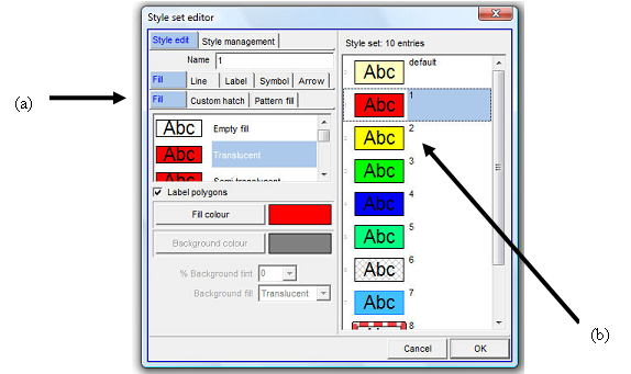
The right column shows the styles with their polygon, line, point and text definition. You can change each of these features individually by selecting (a) the feature and (b) the style number.
To add more units to the existing style set (upto 256): In the Style set editor window move to the unit, after which you want to add new styles (for example, the last one) > Style management > Edit set > Create new styles > Add new styles window: Number of new styles > OK
There is a wide range of options to modify the style, such as change of name, colour, transparency, appearance of label, width of line, appearance of line, point symbol etc. Most of these are self-explanatory, and can be accessed through the Style set editor. Also, created styles can be copied (through Style management).
6.2.4 Selection of Style Library for Display of Individual Layers
Each time you load a layer and want to apply the defined style, you have to assign the layer to the style:
After having loaded the layer (Add layer): Main menu > Project manager window: Components > Layers > Style > Style set > Select Library

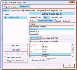
If specific cases, you might not refer to the style (in your DRA file), but a data column in your attached database (DBF file):
After having loaded the layer (Add layer): Main menu > Project manager window: Components > Layers > Style > Style set > Define library > Assign according to
> Database > Data column > Select TYPE or similar field, which contains the code for the style set > OK
6.2.5 Project Library
If you like to change the style only for the current map, you can do so by changing the style of the current project: only (so-called project style set):
Right-mouse > Project manager > Project manager window: Components > Project style set > Continue with the style editor, as explained above > OK
This particular style will be lost, unless you save the entire project (Main menu > File > Save Project).
6.2.6 Creation of New Point Symbols
In exceptional cases you might have to create new symbols as point styles:
- 1. Define new symbol(s) by clearing the project and designing the new symbol with drawing tools:
Main menu > File > Clear > Button tools: Polygon and draw polygons, similarly also lines and points > right-mouse > Save live layer as > Select folder and enter filename > right-mouse > Add layer > Select folder and filename > You might have to choose the right style set to get the correct colours > OK > File > Save screen image > As Enhanced Metafile > Select folder, enter filename > Save
Alternatively, you can use a JPG file (or any other graphics file) and convert it in your graphics program to EMF format.
- 2. Create symbol set:
Main menu > File > System set up > Edit symbols sets > Set up window: New symbol set > Name new symbol set window: Enter new name > OK
- 3. Integrate symbol to symbol set:
Main menu > File > System set up > Edit symbols sets > Set up window: Import > Select files of type: emf > Select folder and file > OK > Click on items on both listings, so number of symbols at top is correct
- 4. Export symbol set and create SYB file:
Still in the Set up window: Export symbol set > Select folder, where MMM.exe is located (normally: C:\Map Maker) > Enter filename (preferably, same as before) > OK
If you want to delete, you have to delete both in Set up window (Main menu > File > System set up > Edit symbols sets > Set up window: Delete symbol set) and the SYB file in Windows Explorer in folder C:\Map Maker.
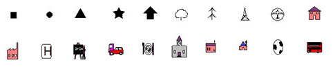
An Agric symbol set has been created for the project to symbolize agricultural patterns and potential on the maps. It can be requested from LUPMIS/TCPD-HQ (see also Annex 1.1.1 for installation and Annex 11 for distribution CD).
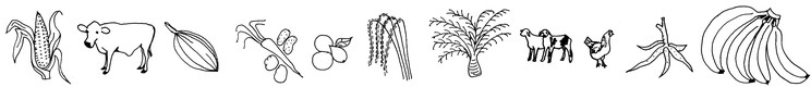
and:

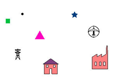
With these kinds of symbol sets, you can create indicative distribution maps, as below:

6.2.7 Bands for Graded Features
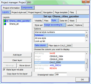
If you have quantitative data in a thematic map, you can also use the option to assign graded colours or symbols based on the numeric data, instead of using styles.
Right-mouse > Project manager > Project manager window: Layer > Select layer > Style > Assign according to
> Database >
Data column > Select column containing the data >
Filter data in
. > Either: New filter (> Select folder > Write new file name > Save >) or: Choose filter > Select folder and file > Edit filter > )
If you have points to display according to their value:
Data bands window: Filter > Specify how many bands (classes) you want > Tick both Use symbol colours and size rather than styles and Graded colours and size >

Under Symbol type a listing should appear. (If it does not appear, untick these two options, and re-tick again) > Select the symbol > OK >
Still in Data bands window: Numerical bands > You can specify the quantitative width of each band by clicking and dragging the drag button on each threshold > OK > OK

The definition of this grading scale has been saved in a filter (txt file), not in a style legend.
6.2.8 Change Current (Project) Style
If you are in live layer, the project style is applied, not a specific style. You are able to change the project style set:
In live layer mode: Edit-tool (at toolbar left) > Click on any polygon > Polygon window: Styles > Edit project style set > Style set editor window: Style management > Import style set and overwrite > Choose style set window: Select style set > OK > OK > OK
6.2.9 Load Data to Style Field
You can assign style numbers to units:
A) Either, individually in live layer mode by the Edit-tool (at toolbar left) > Select the unit > Styles > Select the style (class) > OK

B) Or, by filtering many units and make an assignment for all of the selected, through:
Copy layer to live layer > Main menu > Edit > Show Selection Manager > Selection Manager window: Find objects by criteria > Find > Search by criteria window: Double-click on the field under Terms and complete search condition under Criteria Statement > The green valid tick should appear > OK

Selection Manager window: Listing all selected units > Actions > Basic operations > Set all objects to one style > Choose style window: Select style number > OK > X
Dont forget to save at the end.

