LUPMIS - GIS User Manual for Land Use Planning
Main menu:
- Home Page
- 0. Rationale
- 1. GIS handling
- 2. GIS data entry
- 2.1 Create new layer
- 2.2 Digitize line
- 2.3 Digitize point
- 2.4 Digitize polygon
- 2.5 Edit existing layer
- 2.6 Delete feature
- 2.7 Split line
- 2.8 Split polygon
- 2.9 Merge lines from different layers
- 2.10 Unite lines
- 2.11 Snap lines
- 2.12 Join polygons
- 2.13 Extend polygon
- 2.14 Insert island
- 2.15 Define unit surrounding islands
- 2.16 Create 'doughnut'
- 2.17 Fill 'doughnut' polygon
- 2.18 Fill polygon with 'holes'
- 2.19 Digitize parcels from sector layout
- 3. GIS operations
- 3.1 Create buffer
- 3.2 Create exclusion zone
- 3.3 Overlay units
- 3.4 Convert line to polygon
- 3.5 Derive statistics (area size, length)
- 3.6 Clip unit according to other unit
- 3.7 Create geographic grid
- 3.8 Move entire vector map
- 3.9 Move or copy individual features on a map
- 3.10 Adjust polygon to line
- 3.11 Convert points to polygon
- 3.12 Define by distance
- 3.13 Create multiple objects
- 3.14 Transfer styles from one layer to another
- 4. Attribute database
- 4.1 Start with database
- 4.2 Import database
- 4.3 Display database information
- 4.4 Enter attribute data
- 4.5 Attribute matrix of multiple layers
- 4.6 Seeds
- 4.7 Repair attribute data
- 4.8 Merge lines with attached database
- 4.9 Transfer attribute data from points to polygons
- 4.10 Copy styles, labels, attributes
- 5. Conversion of data
- 5.1 Points
- 5.1.1 Import list of points from text file
- 5.1.2 Import list of points from Excel file
- 5.1.3 Convert point coordinates between projections
- 5.1.4 Convert point coordinates from Ghana War Office (feet)
- 5.1.5 Convert point coordinates from Ghana Clark 1880 (feet)
- 5.1.6 Track with GPS
- 5.1.7 Download GPS track from Garmin
- 5.1.8 Download GPS track from PDA
- 5.2 Vector maps
- 5.3 Raster maps
- 5.3.1 Import raster map from external source
- 5.3.2 Quality-check raster file
- 5.3.3 Georeference scanned map
- 5.3.4 Re-georeference image
- 5.3.5 Load sector layout map
- 5.3.6 Shift raster map
- 5.3.7 Download Google Earth image
- 5.3.8 Clipping and masking images
- 5.3.9 Enhance georeferenced image
- 5.3.10 Batch-convert raster images
- 5.4 Communication with other GIS programs
- 5.4.1 Import GIS data from SHP format
- 5.4.2 Import GIS data from E00 format
- 5.4.3 Import GIS data from AutoCAD
- 5.4.4 Export LUPMIS data to other programs
- 5.4.5 Export GIS to AutoCAD
- 5.4.6 Change a shape file to GPX
- 5.4.7 Transfer GIS data to other LUPMIS installations
- 5.4.8 Digitize lines in Google Earth
- 5.5 Terrain data
- 5.1 Points
- 6. Presentation
- 7. GIS for land use planning
- 8. LUPMIS Tools
- 9. Databases
- Annexes
- A1. Map Maker setup
- A2. Background to cartography and raster images
- A3. Glosssary
- A4. Troubleshooting
- A5. Styles
- A6. Classification for land use mapping and planning
- A7. GIS utilities
- A8. Map projection parameters
- A9. Maps in pilot areas
- A10.Standards
- A11. LUPMIS distribution CD
- A12. Garmin GPS
- A13. Training
- A14. ArcView
- A15. Population statistics
- A16. Entry and display of survey data
- A17. External exercises
- A18. Programming
- A19. Paper sizes
- A20. Various IT advices
- A21. Site map and references
7.6.3 GIS Process for Local Plan
7. GIS for land use planning > 7.6 Local Plan
7.6.3 GIS Process for Local Plan
Level of expertise required for this Chapter: Advanced; specifically for LUPMIS @ TCPD
General process: Main roads + Minor (access) roads (lines --> buffers) + Parcels + Separation of roads + Styles (classes) + Labels (reference numbers: UPN).
These procedures have a high demand on processor and memory of your computer. Have a look at the technical notes ( Chapter 7.6.5) for solving any technical problems encountered.
Before you start, load the classification (classes) for Local Plan (style library LocalPlan_ tl, see Annex 6.5).
1. In Map Maker, trace the main roads within this subsector. Roads can start or end beyond the edges of the subsector.

- - - - -
2. Select all these roads with the Select-tool from the toolbar left. Be sure, you do not select the underlying sector polygon.
If any polygon is selected, Remove from selection in the Selection Manager.

- - - - -
3. Form polygons as buffers along these road lines:
Main menu > Edit > Show selection manager > Selection Manager window: Actions > Polygon manipulation > Generate buffer zones >

> Generate buffer zones window: Enter the width of the buffer zone:
- 6 m for a road in a residential area,
- 8 m for a main road in a residential area,
- 10-20 m for main urban roads,
- 40 m for highways,
- 60 m for main highways
> Tick Generate as polygons > Untick Keep original objects > Select External buffer > Untick Keep residual polygons (see sample below) > OK

Save this intermediate layer in a temporary file.
Alternatively, you can create a buffer for each individual line, when you digitize it: Right-mouse, when just finishing the line > Action > Create buffer > same options as above > OK

Note: If there are problems with road buffering, clean (tidy) the road buffer, before you intersect in the next step: Right-mouse > Live layer options > Tidying > Remove segments smaller than > 2 m > OK, see also technical notes in chapters 7.5.5 and 7.6.5.
- - - - -
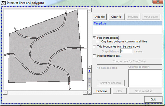
4. Intersect the roads with the sector polygon to have a clean topology (no overlapping polygons):
Main menu > Utilities > Vector utilities > Intersect/Unite lines >

Intersect lines and polygons window: Add file > Select folder and file from above > Open > Tick: Find intersections > Execute > Save result as
> Specify an intermediate temporay file > Save > Quit
Load this new temporary file into the live layer

In live layer mode: Right-mouse > Live layer actions > Tidying > Basic tidy > OK > right-mouse > Live layer actions > Tidying > Tidy polygon topology > OK
Delete the buffer parts, which are outside the sector (Select-tool > Delete).
Note: If there are problems during or after the process in the Intersect lines and polygons window, repeat this process with option Tidy boundaries (in the Intersect lines and polygons window) turned on.
Alternatively, but recommended only for smaller units, you can clip existing features according to the sector outline by: In live layer, right-mouse > Live layer actions > Live layer actions window: Extent > Trim vector to polygons > OK > Polygon file > Select file with sector > Open > OK
- - - - -
5. In most cases, there are more roads (for example, minor roads) within this sector, which have to be digitized as well. Repeat steps 1-4, with a smaller buffer width, e.g. 6 m.
- - - - -
6. Check all junctions, if there is any need for cleaning up

You do this with the Join-tool from the toolbar left.

Save this live layer in an intermediate file, and reload it again live layer.
- - - - -
7. If built-up structures (for example, houses) already exist in this area, it has to be decided by the planners, if the new plan (future structure):
- Either: Incorporates these (The display of existing structure or land use will then be useful as a background layer, for example, at houses already built, permits already issued),
- Or: Plan without their considerations, i.e. accept their demolition (for example, at highway construction)
The detailed land use map (see Chapter 7.3) will be useful for these decisions.
- - - - -
8. You are now ready to define parcels, mainly with the Cutter-tool from the toolbar left.
You can also join two units again, with the Join-tool from the toolbar left.
Frequently, save your work in temporary files.
- - - - -
9. Once you have designed all the parcels, you should separate the road polygons, because the main Local Plan layer should contain only parcels as polygons. You can save the road buffers (also any other polygons, such as water bodies etc) in a separate file.
- 9.1 From the original file, you select all road parcels, delete them and save the remaining (i.e. parcel) polygons in a new file.
- 9.2 Again, from the original file (!), you select all road polygons, but delete all the other (parcel) polygons. Only the road polygons should be left, and save these to a new road layer file. These road polygons will serve as the basis for digitizing the road lines (see Chapter 7.8.3).
Alternatively, if you dont have the roads as polygons in your Local Plan layer, you can use the overlay module (Main menu > Utilities > Vector utilities > Intersect /Unite files > Intersect lines and polygons window) to overlay all parcel polygons with another file of the entire area (1 polygon) .
- - - - -
10. Assign land use, with style numbers
Land use for each parcel should be derived from the Structure Plan, from planners experiences, from participatory contributions by the District Assembly, stakeholders and local population. This information (or parcel assignment) will then in an automated process run in the permit process (see Chapter 7.7).
- 10.1 As this is to be a relatively homogenous area (for example, residential), you will first assign all units to the use (or zone) as defined and approved in the Structure Plan. This process is called inheriting classes from the Structure Plan to the Local Plan.
In live layer: Right-mouse > Live layer actions > Live layer actions window: Spatial queries > Inherit attributes from other file > OK > Inherit attributes from other file window: Polygons files > Select folder and file of Structure Plan layer > Open > Tick: Inherit styles > OK
- 10.2 You can then assign specific numbers (styles) to the other units (for example, commercial, industrial, warehouse etc). See Annex 6.5 for Local Plan styles.
In live layer > right-mouse > Live layer actions > Live layer actions window: Basic operations > Set all objects to one style > OK > Choose style window: Select unit (style) > OK
Edit-tool (at toolbar left) > Select parcel with single click > Polygon window: Styles > Select unit (style) > OK
Alternatively, you can select more than one unit, and assign through the Selection Manager (Action > Basic operations > Set all objects to one style)

- - - - -
11. Following the Unique Parcel Numbering (UPN) system, each parcel has to have a unique code, which will be stored in the Display field of each parcel. The full procedure to define and assign the UPN is explained in Chapter 7.8.1.
- - - - -
12. Dont forget to save.
- - - - -
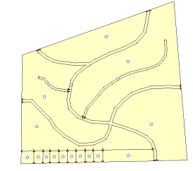
The sample map below demonstrates the basic features of a Local Plan, here of the Opeikuma-Kumbe area west of Kasoa. The actual Local Plan of this area might have a different layout and more details. It will be larger, and have marginalia and legend (see Chapter 7.5.4).

After parcel numbers have been inserted (see Chapter 7.8.1 about Unique Parcel Numbers), a more detailed view with UPN can look like this:


Sub-Menu:
- 7.6.1 Concept of Local Plan
- 7.6.2 Workplan for Local Plan
- 7.6.3 GIS Process for Local Plan ←
- 7.6.4 Layout of Local Plan
- 7.6.5 Technical notes for Local Plan